


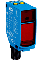
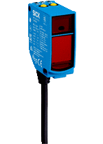
Technical drawings

Connection type

Connection diagram Cd-364

Characteristic curve WT9-3, red light, 350 mm

Light spot size WT9-3, red light, 350 mm

Sensing range diagram WT9-3, red light, 350 mm

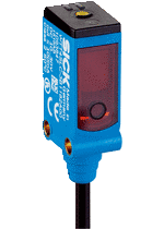
Adjustments Single teach-in button

Adjustments Potentiometer

Dimensional drawing WT9-3
Sản phẩm tương tự
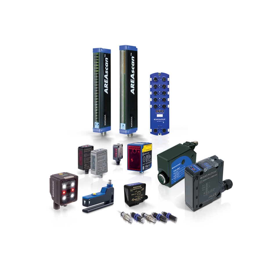
Photoelectric sensors
Photoelectric sensors

Photoelectric sensors

Photoelectric sensors
Photoelectric sensors

Photoelectric sensors
Photoelectric sensors

Photoelectric sensors