


Key Commercial Data
| Orderkey | 3002371 |
|---|---|
| Packing unit | 25 pc |
| Minimum order quantity | 25 pc |
| Note | Made to Order (non-returnable) |
| GTIN | 4055626430881 |
| Weight per Piece (excluding packing) | 9.990 g |
| Custom tariff number | 85369010 |
| Country of origin | IN (India) |
General
| Note | In the end application, the applicable safety regulations for overload and short-circuit protection on the connected conductors must be considered. |
|---|---|
| Number of levels | 1 |
| Number of connections | 5 |
| Nominal cross section | 16 mm² |
| Color | gray |
| Insulating material | PA |
| Flammability rating according to UL 94 | V0 |
| Rated surge voltage | 8 kV |
| Degree of pollution | 2 |
| Overvoltage category | III |
| Insulating material group | I |
| Maximum power dissipation for nominal condition | 4.06 W (the value is multiplied when connecting multiple levels) |
| Connection method | Screw connection |
| Connection in acc. with standard | IEC 60947-7-1 |
| Maximum load current | 101 A (The maximum load current must not be exceeded by the total current of all connected conductors.) |
| Nominal current IN | 101 A |
| Nominal voltage UN | 1000 V |
| Connection method | Push-in connection |
| Connection in acc. with standard | IEC 60947-7-1 |
| Maximum load current | 57 A |
| Nominal current IN | 57 A |
| Nominal voltage UN | 1000 V |
| Open side panel | No |
| Back of the hand protection | guaranteed |
| Finger protection | guaranteed |
| Result of surge voltage test | Test passed |
| Surge voltage test setpoint | 9.8 kV |
| Result of power-frequency withstand voltage test | Test passed |
| Power frequency withstand voltage setpoint | 2.2 kV |
| Result of the test for mechanical stability of terminal points (5 x conductor connection) | Test passed |
| Result of bending test | Test passed |
| Bending test rotation speed | 10 rpm |
| Bending test turns | 135 |
| Bending test conductor cross section/weight | 2.5 mm² / 0.7 kg |
| 10 mm² / 2 kg | |
| 35 mm² / 6.8 kg | |
| Tensile test result | Test passed |
| Conductor cross section tensile test | 2.5 mm² |
| Tractive force setpoint | 50 N |
| Conductor cross section tensile test | 10 mm² |
| Tractive force setpoint | 90 N |
| Conductor cross section tensile test | 35 mm² |
| Tractive force setpoint | 190 N |
| Result of tight fit on support | Test passed |
| Tight fit on carrier | NS 35 |
| Setpoint | 5 N |
| Result of voltage-drop test | Test passed |
| Requirements, voltage drop | ≤ 1.6 mV |
| Result of temperature-rise test | Test passed |
| Short circuit stability result | Test passed |
| Conductor cross section short circuit testing | 10 mm² |
| Short-time current | 1.2 kA |
| Conductor cross section short circuit testing | 16 mm² |
| Short-time current | 1.92 kA |
| Conductor cross section short circuit testing | 35 mm² |
| Short-time current | 4.2 kA |
| Result of aging test | Test passed |
| Ageing test for screwless modular terminal block temperature cycles | 192 |
| Result of thermal test | Test passed |
| Proof of thermal characteristics (needle flame) effective duration | 30 s |
| Oscillation, broadband noise test result | Test passed |
| Test specification, oscillation, broadband noise | DIN EN 50155 (VDE 0115-200):2008-03 |
| Test spectrum | Service life test category 2, bogie-mounted |
| Test frequency | f1= 5 Hz to f2= 250 Hz |
| ASD level | 6.12 (m/s2)2/Hz |
| Acceleration | 3.12 g |
| Test duration per axis | 5 h |
| Test directions | X-, Y- and Z-axis |
| Shock test result | Test passed |
| Test specification, shock test | DIN EN 50155 (VDE 0115-200):2008-03 |
| Shock form | Half-sine |
| Acceleration | 30g |
| Shock duration | 18 ms |
| Number of shocks per direction | 3 |
| Test directions | X-, Y- and Z-axis (pos. and neg.) |
| Relative insulation material temperature index (Elec., UL 746 B) | 130 °C |
| Temperature index of insulation material (DIN EN 60216-1 (VDE 0304-21)) | 130 °C |
| Static insulating material application in cold | -60 °C |
| Behavior in fire for rail vehicles (DIN 5510-2) | Test passed |
| Flame test method (DIN EN 60695-11-10) | V0 |
| Oxygen index (DIN EN ISO 4589-2) | >32 % |
| NF F16-101, NF F10-102 Class I | 2 |
| NF F16-101, NF F10-102 Class F | 2 |
| Surface flammability NFPA 130 (ASTM E 162) | passed |
| Specific optical density of smoke NFPA 130 (ASTM E 662) | passed |
| Smoke gas toxicity NFPA 130 (SMP 800C) | passed |
| Calorimetric heat release NFPA 130 (ASTM E 1354) | 28 MJ/kg |
| Fire protection for rail vehicles (DIN EN 45545-2) R22 | HL 1 – HL 3 |
| Fire protection for rail vehicles (DIN EN 45545-2) R23 | HL 1 – HL 3 |
| Fire protection for rail vehicles (DIN EN 45545-2) R24 | HL 1 – HL 3 |
| Fire protection for rail vehicles (DIN EN 45545-2) R26 | HL 1 – HL 3 |
Connection data
| Connection method | Screw connection |
|---|---|
| Connection in acc. with standard | IEC 60947-7-1 |
| Screw thread | M6 |
| Tightening torque, min | 3.2 Nm |
| Tightening torque max | 3.7 Nm |
| Stripping length | 18 mm |
| Conductor cross section solid min. | 10 mm² |
| Conductor cross section solid max. | 35 mm² |
| Conductor cross section AWG min. | 8 |
| Conductor cross section AWG max. | 2 |
| Conductor cross section flexible min. | 10 mm² |
| Conductor cross section flexible max. | 35 mm² |
| Min. AWG conductor cross section, flexible | 8 |
| Max. AWG conductor cross section, flexible | 2 |
| Conductor cross section flexible, with ferrule without plastic sleeve min. | 10 mm² |
| Conductor cross section flexible, with ferrule without plastic sleeve max. | 35 mm² |
| Conductor cross section flexible, with ferrule with plastic sleeve min. | 10 mm² |
| Conductor cross section flexible, with ferrule with plastic sleeve max. | 35 mm² |
| 2 conductors with same cross section, solid min. | 1.5 mm² |
| 2 conductors with same cross section, solid max. | 16 mm² |
| Two conductors with the same cross section, AWG solid min. | 16 |
| Two conductors with the same cross section, AWG solid max. | 6 |
| 2 conductors with same cross section, stranded min. | 1.5 mm² |
| 2 conductors with same cross section, stranded max. | 10 mm² |
| Two conductors with the same cross section, AWG stranded, min. | 16 |
| Two conductors with the same cross section, AWG stranded, max. | 8 |
| 2 conductors with same cross section, stranded, ferrules without plastic sleeve, min. | 1.5 mm² |
| 2 conductors with same cross section, stranded, ferrules without plastic sleeve, max. | 10 mm² |
| Conductor cross section solid min. | 1 mm² |
| Conductor cross section solid max. | 16 mm² |
| Conductor cross section AWG min. | 16 |
| Conductor cross section AWG max. | 6 |
| Conductor cross section flexible min. | 4 mm² |
| Conductor cross section flexible max. | 10 mm² |
| Internal cylindrical gage | B9 |
| Connection method | Push-in connection |
| Connection in acc. with standard | IEC 60947-7-1 |
| Conductor cross section solid min. | 2.5 mm² |
| Conductor cross section solid max. | 16 mm² |
| Conductor cross section AWG min. | 20 |
| Conductor cross section AWG max. | 6 |
| Conductor cross section flexible min. | 2.5 mm² |
| Conductor cross section flexible max. | 10 mm² |
| Min. AWG conductor cross section, flexible | 20 |
| Max. AWG conductor cross section, flexible | 8 |
| Conductor cross section flexible, with ferrule without plastic sleeve min. | 2.5 mm² |
| Conductor cross section flexible, with ferrule without plastic sleeve max. | 10 mm² |
| Conductor cross section flexible, with ferrule with plastic sleeve min. | 2.5 mm² |
| Conductor cross section flexible, with ferrule with plastic sleeve max. | 10 mm² |
Standards and Regulations
| Connection in acc. with standard | IEC 60947-7-1 |
|---|---|
| IEC 60947-7-1 | |
| Flammability rating according to UL 94 | V0 |
| Fire protection for rail vehicles (DIN EN 45545-2) R22 | HL 1 – HL 3 |
| Fire protection for rail vehicles (DIN EN 45545-2) R23 | HL 1 – HL 3 |
| Fire protection for rail vehicles (DIN EN 45545-2) R24 | HL 1 – HL 3 |
| Fire protection for rail vehicles (DIN EN 45545-2) R26 | HL 1 – HL 3 |
Sản phẩm tương tự
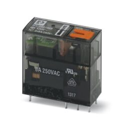
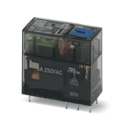
Industrial Relays

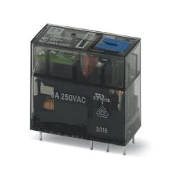
Industrial Relays
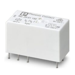
Industrial Relays
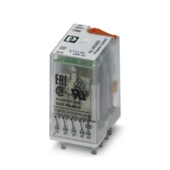
Industrial Relays
Industrial Relays
Industrial Relays
Industrial Relays

Industrial Relays