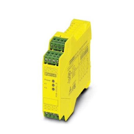
PSR-SPP- 24UC/ESA2/4X1/1X2/B 2963954 PHOENIX CONTACT Safety relays
PSR-SPP- 24UC/ESA2/4X1/1X2/B 2963954 PHOENIX CONTACT Safety relays
Safety relays
-
sản phẩm chính hãng, MỚI 100% CHƯA SỬ DỤNG
-
SẢN PHẨM LUÔN ĐƯỢC KIỂM TRA TRƯỚC KHI XUẤT KHO
-
BẢO HÀNH 12 THÁNG ĐỐI VỚI LỖI CỦA NHÀ SẢN XUẤT / HOẶC THEO CHÍNH SÁCH CỦA SẢN PHẨM DO TRƯỜNG THỊNH PHÂN PHỐI
-
HỖ TRỢ KỸ THUẬT 24/7
-
MIỄN PHÍ GIAO HÀNG ĐỐI VỚI CÁC ĐƠN HÀNG TỪ 8,000,000VNĐ
Liên hệ:
Key Commercial Data
| Orderkey | 2963954 |
|---|---|
| Packing unit | 1 pc |
| Catalog page | Page 260 (C-6-2017) |
| GTIN | 4017918904821 |
| Weight per Piece (excluding packing) | 194.380 g |
| Custom tariff number | 85371098 |
| Country of origin | DE (Germany) |
Note
| Utilization restriction | EMC: class A product, see manufacturer’s declaration in the download area |
|---|
Ambient conditions
| Ambient temperature (operation) | -20 °C … 65 °C (observe derating) |
|---|---|
| Ambient temperature (storage/transport) | -40 °C … 70 °C |
| Max. permissible relative humidity (operation) | 75 % (on average, 85% infrequently, non-condensing) |
| Max. permissible humidity (storage/transport) | 75 % (on average, 85% infrequently, non-condensing) |
| Maximum altitude | ≤ 2000 m (Above sea level) |
Input data
| Rated control circuit supply voltage US | 24 V AC/DC -15 % / +10 % |
|---|---|
| Rated control supply current IS | typ. 140 mA AC |
| typ. 65 mA DC | |
| Power consumption at US | typ. 3.36 W (AC) |
| typ. 1.56 W (DC) | |
| Inrush current | 2 A (Δt = 10 ms at Us) |
| < 40 mA (with Us/Ixto S34) | |
| Current consumption | < 50 mA (with Us/Ixto S12) |
| 0 mA (with Us/Ixto S34) | |
| Voltage at input/start and feedback circuit | 24 V DC -15 % / +10 % |
| Typical response time | < 65 ms (automatic start) |
| < 40 ms (manual start) | |
| Typ. starting time with Us | < 65 ms (when controlled via A1) |
| Typical release time | < 45 ms (when controlled via S12) |
| < 200 ms (when controlled via A1) | |
| Recovery time | < 1 s |
| Operating voltage display | 1 x green LED |
| Status display | 2 x green LEDs |
| Protective circuit | Surge protection Suppressor diode |
| Protection against polarity reversal for rated control circuit supply voltage | |
| Maximum switching frequency | 1 Hz |
| Max. permissible overall conductor resistance | approx. 22 Ω (Input and start circuits at US) |
| Filter time | 2 ms (at A1 in the event of voltage dips at Us) |
| max. 1.5 ms (at S12; test pulse width) | |
| 7.5 ms (at S12; test pulse rate) | |
| Test pulse rate = 5 x Test pulse width |
Output data
| Contact type | 4 enabling current paths |
|---|---|
| 1 signaling current path | |
| Contact material | AgSnO2 |
| Maximum switching voltage | 250 V AC/DC (Observe the load curve) |
| Minimum switching voltage | 5 V AC/DC |
| Limiting continuous current | 6 A (N/O contact, pay attention to the derating) |
| 6 A (N/C contact) | |
| Maximum inrush current | 20 A (Δt 100 ms) |
| Inrush current, minimum | 10 mA |
| Sq. Total current | 72 A2(observe derating) |
| Interrupting rating (ohmic load) max. | 144 W (24 V DC, τ = 0 ms) |
| 288 W (48 V DC, τ = 0 ms) | |
| 110 W (110 V DC, τ = 0 ms) | |
| 88 W (220 V DC, τ = 0 ms) | |
| 1500 VA (250 V AC, τ = 0 ms) | |
| Maximum interrupting rating (inductive load) | 42 W (24 V DC, τ = 40 ms) |
| 42 W (48 V DC, τ = 40 ms) | |
| 42 W (110 V DC, τ = 40 ms) | |
| 42 W (220 V DC, τ = 40 ms) | |
| Switching capacity min. | 50 mW |
| Mechanical service life | 10x 106cycles |
| Switching capacity (360/h cycles) | 4 A (24 V DC) |
| 4 A (230 V AC) | |
| Output fuse | 10 A gL/gG (N/O contact) |
| 6 A gL/gG (N/C contact) |
Sản phẩm tương tự
Industrial Relays
Industrial Relays
Industrial Relays
Industrial Relays
Industrial Relays
Industrial Relays

