


PSR-MC42-2NO-1DO-24DC-SC 2702901 PHOENIX CONTACT Safety relay with IO-Link for emergency stop, safety doors,..

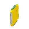
PSR-MC42-2NO-1DO-24DC-SC 2702901 PHOENIX CONTACT Safety relay with IO-Link for emergency stop, safety doors,..
Safety relay with IO-Link for emergency stop, safety doors, and light grids, up to SILCL 3, Cat. 4, PL e, 2 sensor circuits, automatic or manual, monitored start, 2 enabling current paths, 1 signal output, U
Liên hệ:
Key Commercial Data
| Orderkey | 2702901 |
|---|---|
| Packing unit | 1 pc |
| Catalog page | Page 224 (C-6-2019) |
| GTIN | 4055626458540 |
| Weight per Piece (excluding packing) | 180.000 g |
| Custom tariff number | 85371098 |
| Country of origin | DE (Germany) |


Note
| Utilization restriction | EMC: class A product, see manufacturer’s declaration in the download area |
|---|
Ambient conditions
| Ambient temperature (operation) | -25 °C … 60 °C (observe derating) |
|---|---|
| Ambient temperature (storage/transport) | -40 °C … 85 °C |
| Max. permissible relative humidity (operation) | 75 % (on average, 85% infrequently, non-condensing) |
| Max. permissible humidity (storage/transport) | 75 % (on average, 85% infrequently, non-condensing) |
| Maximum altitude | ≤ 2000 m (Above sea level) |
Power supply
| Designation | A1/A2 |
|---|---|
| Rated control circuit supply voltage US | 24 V DC -20 % / +25 % (provide external protection) |
| Rated control supply current IS | typ. 60 mA |
| Power consumption at US | typ. 1.44 W |
| Inrush current | typ. 2.5 A (Δt = 500 µs at Us) |
| Filter time | 1 ms (at A1 in the event of voltage dips at Us) |
| Protective circuit | Serial protection against polarity reversal Suppressor diode |
Supply of the IO-Link ports
| Designation | L+/L- |
|---|---|
| Nominal voltage for I/O supply | 24 V DC -20 % / +25 % (is provided via the IO-Link interface of the IO-Link master.) |
| Current consumption | typ. 16 mA |
| Type of protection | Serial protection against polarity reversal |
| Protective circuit/component | Suppressor diode |
Digital inputs
| Input name | Sensor circuit S0 |
|---|---|
| S12, S22 | |
| Description of the input | safety-related sensor inputs |
| NPN (S12), NPN/PNP (S22) | |
| Number of inputs | 2 |
| Input voltage range “0” signal | 0 V DC … 5 V DC (S12) |
| For S22, see note in “Signal generator connection versions” section. | |
| Input voltage range “1” signal | 11 V DC … 30 V DC |
| Input current range “0” signal | 0 mA … 2 mA (S12, S22) |
| Inrush current | < 5 mA (typ. with USat S12, Δt = 150 ms) |
| < 5 mA (typically with USat S22/24 V, Δt = 500 µs) | |
| > -5 mA (typically with USat S22/0 V, Δt = 500 µs) | |
| Current consumption | < 5 mA (Typically with USat S12) |
| < 5 mA (typically with USat S22/24 V) | |
| > -5 mA (typically with USat S22/0 V) | |
| Filter time | 1.5 ms (Test pulse width of low test pulses) |
| Test pulse rate = 5 x Test pulse width | |
| Deactivate switch-on pulses/light tests for safety applications. | |
| Max. permissible overall conductor resistance | 150 Ω |
| Concurrence input 1/2 | ∞ |
| Protective circuit/component | Suppressor diode |
| Input name | Sensor circuit S1 |
| S32, S42 | |
| Description of the input | safety-related sensor inputs |
| NPN | |
| Number of inputs | 2 |
| Input voltage range “0” signal | 0 V DC … 5 V DC |
| Input voltage range “1” signal | 11 V DC … 30 V DC |
| Input current range “0” signal | 0 mA … 2 mA |
| Inrush current | < 20 mA (typically with US) |
| Current consumption | < 5 mA (typically with US) |
| Filter time | max. 1.5 ms (Test pulse width of low test pulses) |
| Test pulse rate = 5 x Test pulse width | |
| Deactivate switch-on pulses/light tests for safety applications. | |
| Max. permissible overall conductor resistance | 150 Ω |
| Concurrence input 1/2 | ∞ |
| Protective circuit/component | Suppressor diode |
| Input name | Diagnostic input |
| DGN | |
| Description of the input | non-safety-related |
| Number of inputs | 1 |
| Input voltage range | 0 V DC … 30 V DC |
| Current consumption | typ. 30 mA |
| Protective circuit/component | Suppressor diode |
| Input name | Start circuit |
| S34 | |
| Description of the input | NPN (manual start), PNP (autostart) |
| Number of inputs | 1 |
| Input voltage range “1” signal | 19.2 V DC … 30 V DC (manual start, autostart: 0 V) |
| Inrush current | < 10 mA (typically with US, Δt = 100 ms) |
| Current consumption | < 5 mA (typically with USat S34/24 V) |
| > -5 mA (typically with USat S34/0 V) | |
| Max. permissible overall conductor resistance | 150 Ω |
| Protective circuit/component | Suppressor diode |
IO-Link inputs
| Designation | IO-Link |
|---|---|
| Specification | Version 1.1 |
| Transmission speed | 230 kbps (COM3) |
| Cycle Time | 5 ms |
| Process data update | 5 ms |
| Amount of process data | max. 31 Byte (Input data) |
| max. 16 Byte (Output data) | |
| Number of ports | 1 |
| Connection method | Screw connection |
| Connection technology | 3-wire |
| Port type | Class A |
| Input name | C/Q |
| Description of the input | IO-Link switching and communication cable |
| Number of inputs | 1 |
Relay outputs: enabling current path
| Output name | Enabling current path |
|---|---|
| 13/14, 23/24 | |
| Output description | safety-related N/O contacts |
| 2 NO contacts each in series, without delay, floating | |
| Number of outputs | 2 (undelayed) |
| Contact type | 2 enabling current paths |
| Contact material | AgSnO2 |
| Switching voltage | min. 12 V AC/DC |
| max. 250 V AC/DC (Observe the load curve) | |
| Limiting continuous current | 6 A |
| Inrush current | min. 3 mA |
| max. 6 A | |
| Sq. Total current | 72 A2(observe derating) |
| Switching capacity | min. 60 mW |
| Switching frequency | 0.5 Hz |
| Mechanical service life | 10x 106cycles |
| Switching capacity according to IEC 60947-5-1 | 4 A (24 V (DC13)) |
| 5 A (250 V (AC15)) | |
| Output fuse | 6 A gL/gG |
| 4 A gL/gG (for low-demand applications) |
Alarm outputs
| Designation | M1 |
|---|---|
| Output description | PNP |
| non-safety-related | |
| Number of outputs | 1 |
| Voltage | approx. 22 V DC (Us– 2 V) |
| Current | max. 100 mA |
| Maximum inrush current | 500 mA (Δt = 1 ms at Us) |
| Protective circuit/component | Suppressor diode |
Times
| Typical pickup time at US | < 250 ms (when controlled via A1) |
|---|---|
| Typical response time at US | < 220 ms (automatic start) |
| < 175 ms (manual, monitored start) | |
| Typical release time at US | < 20 ms (on demand via the sensor circuit) |
| < 20 ms (on demand via A1) | |
| Restart time | < 1 s (Boot time) |
| Recovery time | < 500 ms |
General
| Relay type | Electromechanical relay with forcibly guided contacts in accordance with IEC/EN 61810-3 (EN 50205) |
|---|---|
| Nominal operating mode | 100% operating factor |
| Net weight | 157.28 g |
| Mounting position | vertical or horizontal |
| Mounting type | DIN rail mounting |
| Assembly instructions | See derating curve |
| Degree of protection | IP20 |
| Min. degree of protection of inst. location | IP54 |
| Housing material | PBT |
| Housing color | yellow |
| Operating voltage display | 1 x green, yellow, red LED |
| Status display | 5x LED green |
Connection data
| Connection method | Screw connection |
|---|---|
| pluggable | Yes |
| Conductor cross section solid min. | 0.2 mm² |
| Conductor cross section solid max. | 2.5 mm² |
| Conductor cross section flexible min. | 0.2 mm² |
| Conductor cross section flexible max. | 2.5 mm² |
| Conductor cross section AWG min. | 24 |
| Conductor cross section AWG max. | 12 |
| Stripping length | 7 mm |
| Screw thread | M3 |
| Torque | 0.5 Nm … 0.6 Nm |
Safety-related characteristic data
| Stop category | 0 |
|---|---|
| Designation | IEC 61508 – High demand |
| Safety Integrity Level (SIL) | 3 |
| Designation | IEC 61508 – Low demand |
| Safety Integrity Level (SIL) | 3 |
| Designation | EN ISO 13849 |
| Performance level (PL) | e (4 A DC13; 5 A AC15; 8760 switching cycles/year) |
| Category | 4 |
| Designation | EN 62061 |
| Safety Integrity Level Claim Limit (SIL CL) | 3 |
Standards and Regulations
| Designation | Air clearances and creepage distances between the power circuits |
|---|---|
| Standards/regulations | DIN EN 60947-1 |
| Rated insulation voltage | 320 V |
| 320 V | |
| Rated surge voltage/insulation | Basic insulation 4 kV between all current paths and housing |
| Safe isolation, reinforced insulation 4 kV between input circuit and enabling current path (13/14) and enabling current path (23/24) | |
| Degree of pollution | 2 |
| Overvoltage category | II |
| Shock | 15g |
| Vibration (operation) | 10 Hz … 150 Hz, 2g |
| Conformance | CE-compliant |
Environmental Product Compliance
| REACh SVHC | Lead 7439-92-1 |
|---|---|
| China RoHS | Environmentally Friendly Use Period = 50 |
| For details about hazardous substances go to tab “Downloads”, Category “Manufacturer’s declaration” |
Classifications
[email protected]
| [email protected] 5.1 | 27371901 |
|---|---|
| [email protected] 6.0 | 27371819 |
| [email protected] 8.0 | 27371819 |
| [email protected] 9.0 | 27371819 |
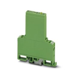
Sản phẩm tương tự

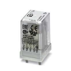
Industrial Relays
EMG 22-REL/KSR-G 24/TRN24/SO62 2944407 PHOENIX CONTACT Relay Module
Industrial Relays
Industrial Relays
Industrial Relays
Industrial Relays
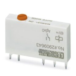
REL-IR/LDP- 12DC/4X21AU 2834083 PHOENIX CONTACT Single relay
Industrial Relays
Industrial Relays
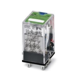
UMK-5REL/KSR-24/230/KRK5S/MSTB 2908666 PHOENIX CONTACT Relay Module