


MINI MCR-2-U-UI-PT 2902021 PHOENIX CONTACT 3-way signal conditioner, with configurable input/output, for ele..
MINI MCR-2-U-UI-PT 2902021 PHOENIX CONTACT 3-way signal conditioner, with configurable input/output, for ele..
3-way signal conditioner, with configurable input/output, for electrical isolation and conversion of analog signals in the mV and V range, unipolar as well as bipolar. Push-in connection technology, standard configuration.
Liên hệ:
Key Commercial Data
| Orderkey | 2902021 |
|---|---|
| Packing unit | 1 pc |
| Catalog page | Page 74 (C-5-2019) |
| GTIN | 4046356651998 |
| Weight per Piece (excluding packing) | 120.000 g |
| Custom tariff number | 85437090 |
| Country of origin | DE (Germany) |


Ambient conditions
| Ambient temperature (operation) | -40 °C … 70 °C |
|---|---|
| Ambient temperature (storage/transport) | -40 °C … 85 °C |
| Permissible humidity (operation) | 5 % … 95 % (non-condensing) |
| Degree of protection | IP20 (not assessed by UL) |
| Noise immunity | EN 61000-6-2 When being exposed to interference, there may be minimal deviations. |
Input data
| Number of inputs | 1 |
|---|---|
| Configurable/programmable | Yes |
| Voltage input signal | -50 mV … 50 mV (via DIP switch) |
| 0 mV … 50 mV (via DIP switch) | |
| -60 mV … 60 mV (via DIP switch) | |
| 0 mV … 60 mV (via DIP switch) | |
| -75 mV … 75 mV (via DIP switch) | |
| 0 mV … 75 mV (via DIP switch) | |
| -80 mV … 80 mV (via DIP switch) | |
| 0 mV … 80 mV (via DIP switch) | |
| -100 mV … 100 mV (via DIP switch) | |
| 0 mV … 100 mV (via DIP switch) | |
| -120 mV … 120 mV (via DIP switch) | |
| 0 mV … 120 mV (via DIP switch) | |
| -150 mV … 150 mV (via DIP switch) | |
| 0 mV … 150 mV (via DIP switch) | |
| -200 mV … 200 mV (via DIP switch) | |
| 0 mV … 200 mV (via DIP switch) | |
| -240 mV … 240 mV (via DIP switch) | |
| 0 mV … 240 mV (via DIP switch) | |
| -300 mV … 300 mV (via DIP switch) | |
| 0 mV … 300 mV (via DIP switch) | |
| -500 mV … 500 mV (via DIP switch) | |
| 0 mV … 500 mV (via DIP switch) | |
| -600 mV … 600 mV (via DIP switch) | |
| 0 mV … 600 mV (via DIP switch) | |
| -750 mV … 750 mV (via DIP switch) | |
| 0 mV … 750 mV (via DIP switch) | |
| -800 mV … 800 mV (via DIP switch) | |
| 0 mV … 800 mV (via DIP switch) | |
| -1 V … 1 V (via DIP switch) | |
| 0 V … 1 V (via DIP switch) | |
| -1.2 V … 1.2 V (via DIP switch) | |
| 0 V … 1.2 V (via DIP switch) | |
| -1.5 V … 1.5 V (via DIP switch) | |
| 0 V … 1.5 V (via DIP switch) | |
| -2 V … 2 V (via DIP switch) | |
| 0 V … 2 V (via DIP switch) | |
| -2.4 V … 2.4 V (via DIP switch) | |
| 0 V … 2.4 V (via DIP switch) | |
| -3 V … 3 V (via DIP switch) | |
| 0 V … 3 V (via DIP switch) | |
| -5 V … 5 V (via DIP switch) | |
| 0 V … 5 V (via DIP switch) | |
| -6 V … 6 V (via DIP switch) | |
| 0 V … 6 V (via DIP switch) | |
| -7.5 V … 7.5 V (via DIP switch) | |
| 0 V … 7.5 V (via DIP switch) | |
| -8 V … 8 V (via DIP switch) | |
| 0 V … 8 V (via DIP switch) | |
| -10 V … 10 V (via DIP switch) | |
| 0 V … 10 V (via DIP switch) | |
| -12 V … 12 V (via DIP switch) | |
| 0 V … 12 V (via DIP switch) | |
| -15 V … 15 V (via DIP switch) | |
| 0 V … 15 V (via DIP switch) | |
| -20 V … 20 V (via DIP switch) | |
| 0 V … 20 V (via DIP switch) | |
| -24 V … 24 V (via DIP switch) | |
| 0 V … 24 V (via DIP switch) | |
| -30 V … 30 V (via DIP switch) | |
| 0 V … 30 V (via DIP switch) | |
| max. input voltage | 33 V |
| Input resistance of voltage input | > 10 kΩ |
Output data
| Number of outputs | 1 |
|---|---|
| Configurable/programmable | Yes |
| Voltage output signal | 0 V … 5 V (via DIP switch) |
| 1 V … 5 V (via DIP switch) | |
| -5 V … 5 V (via DIP switch) | |
| 0 V … 10 V (via DIP switch) | |
| 2 V … 10 V (via DIP switch) | |
| -10 V … 10 V (via DIP switch) | |
| Current output signal | 0 mA … 20 mA (via DIP switch) |
| 4 mA … 20 mA (via DIP switch) | |
| Max. output current | 22 mA |
| Short-circuit current | < 32 mA |
| Load/output load voltage output | ≥ 10 kΩ |
| Load/output load current output | ≤ 600 Ω (at 20 mA) |
| Ripple | < 20 mVPP(at 600 Ω) |
| < 20 mVPP(at 600 Ω) |
Power supply
| Nominal supply voltage | 24 V DC |
|---|---|
| Supply voltage range | 9.6 V DC … 30 V DC (The DIN rail bus connector (ME 6,2 TBUS-2 1,5/5-ST-3,81 GN, Order No. 2869728) can be used to bridge the supply voltage. It can be snapped onto a 35 mm DIN rail according to EN 60715)) |
| Typical current consumption | 25 mA (Current output, at 24 V DC incl. load) |
| 54 mA (Current output, at 12 V DC incl. load) | |
| Power consumption | ≤ 800 mW (at IOUT= 20 mA, 9.6 V DC, 600 Ω load) |
Connection data
| Connection method | Push-in connection |
|---|---|
| Stripping length | 10 mm |
| Conductor cross section solid | 0.14 mm² … 2.5 mm² (with ferrule) |
| 0.14 mm² … 2.5 mm² (without ferrule) | |
| Conductor cross section flexible | 0.14 mm² … 2.5 mm² |
| Conductor cross section AWG | 24 … 12 (flexible) |
General
| No. of channels | 1 |
|---|---|
| Maximum transmission error | ≤ 0.1 % (of final value) |
| Maximum temperature coefficient | 0.01 %/K |
| Limit frequency (3 dB) | 30 Hz (via DIP switch) |
| 5 kHz (via DIP switch) | |
| Step response (10-90%) | < 8.5 ms (with 30 Hz filter) |
| Protective circuit | Transient protection |
| Electrical isolation | Reinforced insulation in accordance with IEC 61010-1 |
| Overvoltage category | II |
| Degree of pollution | 2 |
| Rated insulation voltage | 300 V |
| Test voltage, input/output/supply | 3 kV (50 Hz, 1 min.) |
| Electromagnetic compatibility | Conformance with EMC directive |
| Noise emission | EN 61000-6-4 |
| Noise immunity | EN 61000-6-2 When being exposed to interference, there may be minimal deviations. |
| Color | gray |
| Housing material | PBT |
| Mounting position | any |
| Assembly instructions | The T connector can be used to bridge the supply voltage. It can be snapped onto a 35 mm DIN rail according to EN 60715. |
| Conformance | CE-compliant |
| ATEX | II 3 G Ex nA IIC T4 Gc X |
| UL, USA/Canada | UL 508 Listed |
| Class I, Div. 2, Groups A, B, C, D T6 | |
| Class I, Zone 2, Group IIC T6 | |
| Fire protection for rail vehicles (DIN EN 45545-2) R22 | HL 1 – HL 2 |
| Fire protection for rail vehicles (DIN EN 45545-2) R23 | HL 1 – HL 2 |
| Fire protection for rail vehicles (DIN EN 45545-2) R24 | HL 1 – HL 2 |
EMC data
| Designation | Electromagnetic RF field |
|---|---|
| Standards/regulations | EN 61000-4-3 |
| Designation | Fast transients (burst) |
| Standards/regulations | EN 61000-4-4 |
| Designation | Conducted interferences |
| Standards/regulations | EN 61000-4-6 |
Standards and Regulations
| Electromagnetic compatibility | Conformance with EMC directive |
|---|---|
| Noise emission | EN 61000-6-4 |
| Standards/regulations | EN 61000-4-2 |
| Designation | Electromagnetic RF field |
| Standards/regulations | EN 61000-4-3 |
| EN 61000-4-4 | |
| EN 61000-4-5 | |
| Designation | Conducted interferences |
| Standards/regulations | EN 61000-4-6 |
| Electrical isolation | Reinforced insulation in accordance with IEC 61010-1 |
| Conformance | CE-compliant |
| ATEX | II 3 G Ex nA IIC T4 Gc X |
| UL, USA/Canada | UL 508 Listed |
| Class I, Div. 2, Groups A, B, C, D T6 | |
| Class I, Zone 2, Group IIC T6 |
Environmental Product Compliance
| China RoHS | Environmentally Friendly Use Period = 50 |
|---|---|
| For details about hazardous substances go to tab “Downloads”, Category “Manufacturer’s declaration” |
Classifications
[email protected]
| [email protected] 4.0 | 27210100 |
|---|---|
| [email protected] 4.1 | 27210100 |
| [email protected] 5.0 | 27210100 |
| [email protected] 5.1 | 27210100 |
| [email protected] 6.0 | 27210100 |
| [email protected] 7.0 | 27210120 |
| [email protected] 8.0 | 27210120 |
| [email protected] 9.0 | 27210120 |
Ambient conditions
| Ambient temperature (operation) | -40 °C … 70 °C |
|---|---|
| Ambient temperature (storage/transport) | -40 °C … 85 °C |
| Permissible humidity (operation) | 5 % … 95 % (non-condensing) |
| Degree of protection | IP20 (not assessed by UL) |
| Noise immunity | EN 61000-6-2 When being exposed to interference, there may be minimal deviations. |
Sản phẩm tương tự
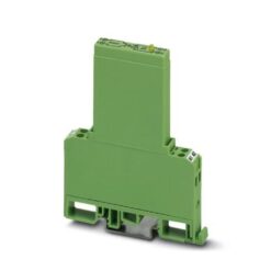
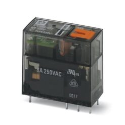
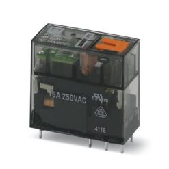
Industrial Relays
Industrial Relays
Industrial Relays
Industrial Relays
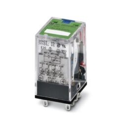
Industrial Relays
REL-IR/LDP- 12DC/4X21AU 2834083 PHOENIX CONTACT Single relay
Industrial Relays
Industrial Relays