


Sản phẩm tương tự
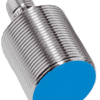
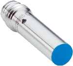
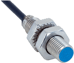
Inductive proximity sensors
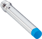
Inductive proximity sensors
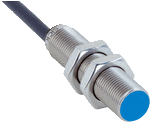
Inductive proximity sensors

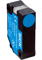
Inductive proximity sensors
Inductive proximity sensors
Inductive proximity sensors
Inductive proximity sensors
Inductive proximity sensors