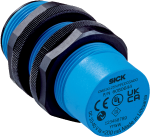
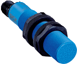
CMB30-25NPPEC0SA00
Capacitive proximity sensors
CMB
-
sản phẩm chính hãng, MỚI 100% CHƯA SỬ DỤNG
-
SẢN PHẨM LUÔN ĐƯỢC KIỂM TRA TRƯỚC KHI XUẤT KHO
-
BẢO HÀNH 12 THÁNG ĐỐI VỚI LỖI CỦA NHÀ SẢN XUẤT / HOẶC THEO CHÍNH SÁCH CỦA SẢN PHẨM DO TRƯỜNG THỊNH PHÂN PHỐI
-
HỖ TRỢ KỸ THUẬT 24/7
-
MIỄN PHÍ GIAO HÀNG ĐỐI VỚI CÁC ĐƠN HÀNG TỪ 8,000,000VNĐ
Liên hệ:
-
Features
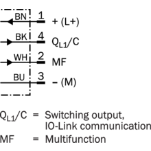
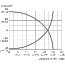
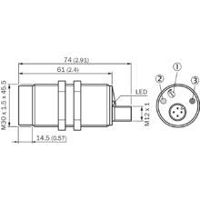
Housing Cylindrical thread design Thread size M30 x 1.5 Diameter Ø 30 mm Sensing range Sn 0 mm … 25 mm Safe sensing range Sa 19.13 mm 1) Installation type Non-flush Switching frequency 50 Hz Connection type Male connector M12, 4-pin Switching output PNP Output function Complementary Output characteristic Wire configurable Electrical wiring DC 4-wire Adjustment Potentiometer, 11 turns (Sensitivity)
Teach-in by wire (Sensitivity)
IO-Link (Sensor parameters and Smart Task functions)
Enclosure rating IP67
IP68 2)
IP69K
Special features Visual adjustment indicator, Smart Task, IO-Link Pin 2 configuration External input, Teach-in, switching signal Items supplied Mounting nut, PA12 plastic (2x)
Screwdriver for potentiometer adjustment (1 x)
- 1) For flush mounting in electrically conductive materials Sa = 0.8 x Sr at temperatures <0 °C and >60 °C.
- 2) 1 m water depth / 60 min.
-
Mechanics/electronics
Supply voltage 10 V DC … 36 V DC Ripple ≤ 10 % 1) Voltage drop ≤ 2 V DC 2) Current consumption ≤ 20 mA 3) Time delay before availability ≤ 300 ms Hysteresis 3 % … 20 % Reproducibility ≤ 5 % 4) 5) Temperature drift (of Sr) ± 10 % EMC EN 61000-4-2 ESD: > 40 kV CD and AD
EN 61000-4-3 Radiated RF: 20 V/m
EN 61000-4-4 burst: +/- 4 kV / 5 kHz
EN 61000-4-5 Surge: Voltage supply > 2 kV with 500 ohm; switching output > 2 kV with 500 ohm
EN 61000-4-6 HF: > 20 Vrms
EN 61000-4-8 mains frequency magnetic fields: Permanent > 60 A/m, 75,9 µ tesla; briefly > 600 A/m, 759 µ tesla
Continuous current Ia ≤ 200 mA Short-circuit protection ✔ Reverse polarity protection ✔ Power-up pulse protection ✔ Shock and vibration resistance EN 60068-2-27 shock resistance Ea: 30 g 11 ms; 3 shocks in each direction of the 3 coordinate axes
IEC 60068-2-31 drop test: 2 times from 1 m, 100 times from 0.5 m
EN 60068-2-6 vibration resistance Fc: 10 Hz … 150 Hz, 1 mm / 15 g
Ambient operating temperature –30 °C … +85 °C 6) Ambient temperature, storage –40 °C … +85 °C Housing material Plastic, PBT Housing length 74 mm Thread length 45.5 mm Tightening torque, max. ≤ 7.5 Nm UL File No. NRKH.E191603 - 1) Of Ub.
- 2) At Ia max.
- 3) Without load.
- 4) Of Sr.
- 5) Ub and Ta constant.
- 6) +120 °C short time, at the front of the sensor.
-
Safety-related parameters
MTTFD 786 years DCavg 0% TM (mission time) 20 years
-
Communication interface
Communication interface IO-Link V1.1 Communication Interface detail COM2 (38,4 kBaud) Cycle time > 5 ms Process data length 4 Byte Process data structure Bit 0 = switching signal QL1
Bit 1 = switching signal QL2
Bit 2 = Sensor switching channel Qint1
Bit 3 = Sensor switching channel Qint2
Bit 4 = Contamination alarm for switching channel Qint1
Bit 5 = Contamination channel for Qint2
Bit 6 = Temperature alarm
Bit 7 = Short-circuit
Bit 16 … 31 = Analog value (digit value, not linearized)
-
Reduction factors
Note The values are reference values which may vary Metal 1 Water 1 PVC Approx. 0.4 Oil Approx. 0.25 Glass 0.6 Ceramics 0.5 Alcohol 0.7 Wood 0.2 … 0.7
-
Installation note
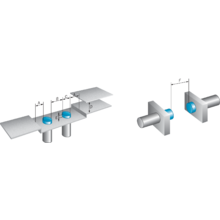
Remark Associated graphic see “Installation” A 30 mm B 60 mm C 30 mm D 75 mm E 14.5 mm
In critical distances, the sensor should be tested in the applicationF 75 mm
-
Smart Task
Smart Task name Base logics Logic function Direct
AND
OR
Window
Hysteresis
Timer function Deactivated
On delay
Off delay
ON and OFF delay
Impulse (one shot)
Inverter Yes Switching signal Switching signal QL1 Switching output Switching signal QL2 Switching output
-
Classifications
eCl@ss 5.0 27270102 eCl@ss 5.1.4 27270102 eCl@ss 6.0 27270102 eCl@ss 6.2 27270102 eCl@ss 7.0 27270102 eCl@ss 8.0 27270102 eCl@ss 8.1 27270102 eCl@ss 9.0 27270102 eCl@ss 10.0 27270102 eCl@ss 11.0 27270102 eCl@ss 12.0 27274201 ETIM 5.0 EC002715 ETIM 6.0 EC002715 ETIM 7.0 EC002715 ETIM 8.0 EC002715 UNSPSC 16.0901 39122230
Sản phẩm tương tự
Capacitive proximity sensors
Capacitive proximity sensors
Capacitive proximity sensors
Capacitive proximity sensors
Capacitive proximity sensors
Capacitive proximity sensors
Capacitive proximity sensors
Capacitive proximity sensors

