

Ambient conditions
| Ambient temperature (operation) | -40 °C … 80 °C |
|---|---|
| Altitude | ≤ 2000 m (amsl (above mean sea level)) |
| Degree of protection | IP20 |
General
| Housing material | Aluminum |
|---|---|
| Standards for cearances and creepage distances | DIN VDE 0110-1 |
| IEC 60664-1 | |
| Mounting type | Connection-specific intermediate plugging |
| Type | Attachment plug |
| Direction of action | Line-Shield/Earth Ground |
Additional descriptions
| Note | To meet the discharge conditions for DC voltages, please note the following information: “The surge protective device should be used together with a transmitter unit, which shuts down in the event of a short-circuit.” |
|---|
Protective circuit
| IEC test classification | C2 |
|---|---|
| C3 | |
| D1 | |
| Maximum continuous voltage UC | 68 V DC |
| 50 V AC | |
| Rated current | 1 A (25 °C) |
| Operating effective current IC at UC | ≤ 1 µA |
| Residual current IPE | ≤ 2 µA |
| Nominal discharge current In (8/20) µs (line-earth) | 10 kA |
| Nominal discharge current In (8/20) µs (line-shield) | 10 kA |
| Pulse discharge current Iimp (10/350) µs (line-earth) | 2.5 kA |
| Pulse discharge current Iimp (10/350) µs (line-shield) | 2.5 kA |
| Output voltage limitation at 1 kV/µs (line-earth) spike | ≤ 650 V |
| Output voltage limitation at 1 kV/µs (line-shield) spike | ≤ 650 V |
| Voltage protection level Up (line-earth) | ≤ 650 V (C2 – 10 kV / 5 kA) |
| Voltage protection level Up (line-shield) | ≤ 650 V (C2 – 10 kV / 5 kA) |
| Response time tA | ≤ 100 ns |
| Input attenuation aE, asym. | typ. 0.1 dB (≤ 20 MHz / 50 Ω) |
| Cut-off frequency fg (3 dB), asym. (shield) in 50 Ohm system | typ. 1 GHz |
| Standing wave ratio SWR in a 50 Ω system | ≤ 1.2 (≤ 200 MHz) |
| Permissible HF power Pmax at VSWR = xx (50 ohm system) | 40 W (VSWR = 1.1) |
| 12 W (VSWR = ∞) | |
| Capacity asymmetrical (shield) | typ. 1.5 pF |
| Surge protection fault message | none |
| Impulse durability (line-earth) | C2 – 10 kV/5 kA |
| C3 – 100 A | |
| D1 – 2.5 kA | |
| Impulse durability (line-shield) | C2 – 10 kV/5 kA |
| C3 – 100 A | |
| D1 – 2.5 kA |
Sản phẩm tương tự
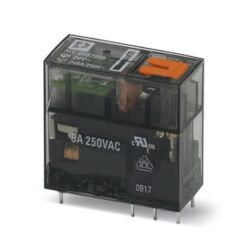
Industrial Relays
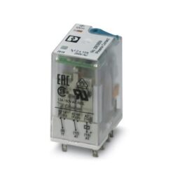
Industrial Relays
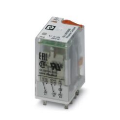
Industrial Relays
Industrial Relays
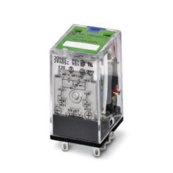
Industrial Relays
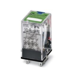
Industrial Relays
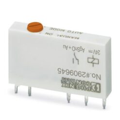
REL-IR/LDP- 12DC/4X21AU 2834083 PHOENIX CONTACT Single relay
Industrial Relays
Industrial Relays
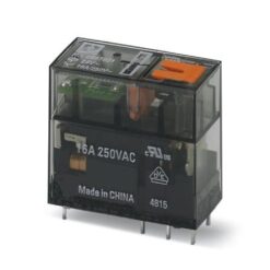
UMK-5REL/KSR-24/230/KRK5S/MSTB 2908666 PHOENIX CONTACT Relay Module