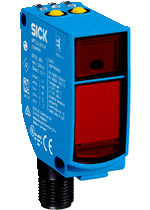
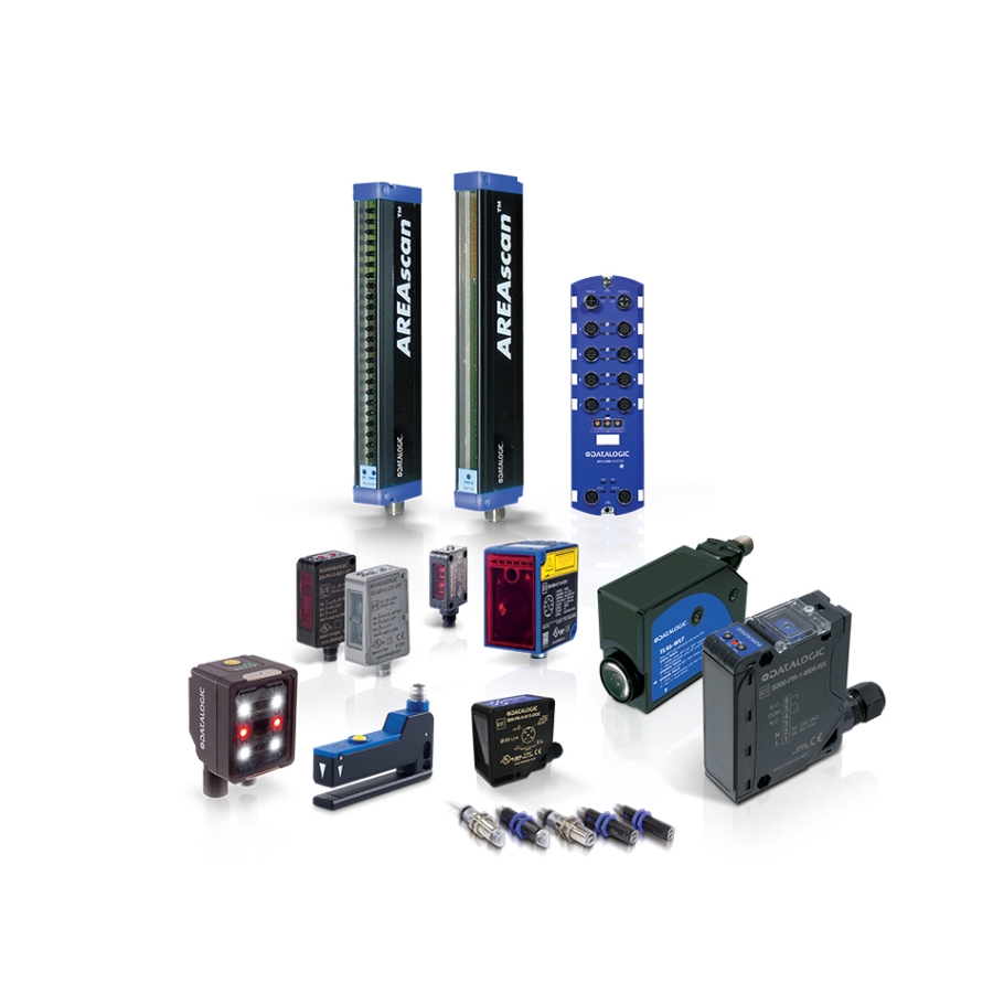
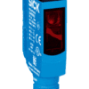
-
Features
Functional principle Through-beam photoelectric sensor Dimensions (W x H x D) 12.2 mm x 52.2 mm x 23.6 mm Housing design (light emission) Rectangular Mounting hole M3 Sensing range max. 0 m … 10 m Sensing range 0 m … 7 m Type of light Visible red light Light source PinPoint LED 1) Light spot size (distance) Ø 25 mm (1 m) Wave length 650 nm Adjustment IO-Link Pin 2 configuration External input, Teach-in input, Detection output, logic output, Device contamination alarm output - 1) Average service life: 100,000 h at TU = +25 °C.
-
Mechanics/electronics
Supply voltage 10 V DC … 30 V DC 1) Ripple < 5 Vpp 2) Current consumption 30 mA 3) Switching output PNP 4) Switching mode Light/dark switching 4) Output current Imax. ≤ 100 mA 5) Response time < 0.5 ms 6) Response time Q/ on Pin 2 300 µs … 450 µs 6) 7) Switching frequency 1,000 Hz 8) Switching frequency Q / to pin 2 ≤ 1,000 Hz 9) Connection type Male connector M12, 4-pin Circuit protection A 10)
B 11)
C 12)
Protection class III Weight 13 g Housing material Plastic, VISTAL® Optics material Plastic, PMMA Enclosure rating IP66
IP67
IP69K
Test input sender off Sender off Ambient operating temperature –40 °C … +60 °C Ambient temperature, storage –40 °C … +75 °C UL File No. NRKH.E181493 Part number of individual components 2055824 WS9-3D2430, 2088124 WE9C-3P2430A00 Repeatability Q/ on Pin 2: 150 µs 7) - 1) Limit values when operated in short-circuit protected network: max. 8 A.
- 2) May not exceed or fall below Uv tolerances.
- 3) Without load.
- 4) Q = light switching.
- 5) At and above Tu 50 °C, a max. load current of Imax. = 50 mA is permitted.
- 6) Signal transit time with resistive load.
- 7) Valid for Q on Pin2, if configured with software.
- 8) With light/dark ratio 1:1.
- 9) With light / dark ratio 1:1, valid for Q on Pin2, if configured with software.
- 10) A = VS connections reverse-polarity protected.
- 11) B = inputs and output reverse-polarity protected.
- 12) C = interference suppression.
-
Safety-related parameters
MTTFD 693 years DCavg 0 %
-
Communication interface
Communication interface IO-Link V1.1 Communication Interface detail COM2 (38,4 kBaud) Cycle time 2.3 ms Process data length 16 Bit Process data structure Bit 0 = switching signal QL1
Bit 1 = switching signal QL2
Bit 2 … 15 = empty
VendorID 26 DeviceID HEX 0x8000E4 DeviceID DEC 8388836
-
Smart Task
Smart Task name Base logics Logic function Direct
AND
OR
WINDOW
Hysteresis
Timer function Deactivated
On delay
Off delay
ON and OFF delay
Impulse (one shot)
Inverter Yes Switching frequency SIO Direct: 1000 Hz 1)
SIO Logic: 1000 Hz 2)
IOL: 900 Hz 3)
Response time SIO Direct: 300 µs … 450 µs 1)
SIO Logic: 500 µs … 600 µs 2)
IOL: 500 µs … 900 µs 3)
Repeatability SIO Direct: 150 µs 1)
SIO Logic: 150 µs 2)
IOL: 400 µs 3)
Switching signal Switching signal QL1 Output type (dependant on the adjusted threshold) Switching signal QL2 Output type (dependant on the adjusted threshold) - 1) SIO Direct: sensor operation in standard I/O mode without IO-Link communication and without using internal sensor logic or time parameters (set to “direct”/”deactivated”).
- 2) SIO Logic: Sensor operation in standard I/O mode without IO-Link communication. Sensor-internal logic or timing parameters plus Automation Functions used.
- 3) IOL: Sensor operation with full IO-Link communication and usage of logic, timing and Automation Function parameters.
-
Diagnosis
Device status Yes Function reserve Yes
-
Classifications
eCl@ss 5.0 27270901 eCl@ss 5.1.4 27270901 eCl@ss 6.0 27270901 eCl@ss 6.2 27270901 eCl@ss 7.0 27270901 eCl@ss 8.0 27270901 eCl@ss 8.1 27270901 eCl@ss 9.0 27270901 eCl@ss 10.0 27270901 eCl@ss 11.0 27270901 eCl@ss 12.0 27270901 ETIM 5.0 EC002716 ETIM 6.0 EC002716 ETIM 7.0 EC002716 ETIM 8.0 EC002716 UNSPSC 16.0901 39121528