

 for Honeywell C300 out..")
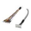
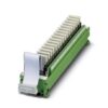
UM- D37SUB/M/HC3/16DO/MR/1/MT 1083697 PHOENIX CONTACT 16-channel relay module (1 NOC) for Honeywell C300 out..
UM- D37SUB/M/HC3/16DO/MR/1/MT 1083697 PHOENIX CONTACT 16-channel relay module (1 NOC) for Honeywell C300 out..
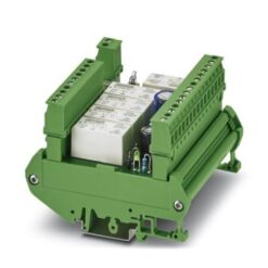
16-channel relay module (1 NOC) for Honeywell C300 output modules. On the control side, the module is controlled via D-SUB 37-pos. or FLK 50-pos. A screw connection with knife disconnection is available on the field side.
Liên hệ:
Key Commercial Data
| Orderkey | 1083697 |
|---|---|
| Packing unit | 1 |
| GTIN | 4055626819198 |
| Custom tariff number | 85364900 |
Note
| Utilization restriction | EMC: class A product, see manufacturer’s declaration in the download area |
|---|---|
| Note | Do not connect adjacent channels to SELV/ PELV and voltages dangerous to the touch. |
| The outputs are not suitable for switching different outer conductors. | |
| No additional touch protection is required when using a SELV/PELV voltage (≤ 25 V AC or 60 V DC). | |
| Against adjacent modules in the support rail direction at least one functional insulation on the output-side is complied with. If the application has higher requirements on the insulation (basic insulation or reinforced insulation), then these must be realized through suitable measures (e. g. partition plates). |
Ambient conditions
| Ambient temperature (operation) | -15 °C … 50 °C |
|---|---|
| Ambient temperature (storage/transport) | -15 °C … 50 °C |
| Maximum altitude | ≤ 2000 m |
| Degree of protection | IP00 |
| ≥ IP54 (Installation location) |
Input data
| Nominal input voltage UN | 24 V DC |
|---|---|
| Input voltage range in reference to UN | 0.85 … 1.1 |
| Typical input current at UN | 9 mA |
| Typical response time | 5 ms |
| Typical release time | 7 ms |
| Protective circuit/component | Damping diode |
| Status display/channel | Yellow LED |
Output data
| Contact type | 1 N/O contact |
|---|---|
| Contact material | AgSnO |
| Maximum switching voltage | 250 V AC/DC |
| Minimum switching voltage | 12 V AC/DC |
| Limiting continuous current | 4 A |
| Min. switching current | 10 mA |
| Interrupting rating (ohmic load) max. | 96 W (at 24 V DC) |
| 20 W (at 48 V DC) | |
| 18 W (at 60 V DC) | |
| 23 W (at 110 V DC) | |
| 37 W (at 220 V DC) | |
| 1000 VA (for 250 V AC) |
General
| Mechanical service life | 2x 10⁷cycles |
|---|---|
| Operating mode | 100% operating factor |
| Mounting position | any |
| Assembly instructions | In rows with zero spacing |
Connection data
| Connection name | Controller level |
|---|---|
| Connection method | D-SUB pin strip |
| Number of connections | 1 |
| Number of positions | 37 |
Connection data 2
| Connection name | Field level |
|---|---|
| Connection method | Screw connection with disconnect knife |
| Stripping length | 8 mm |
| Screw thread | M3 |
| Conductor cross section solid | 0.2 mm² … 4 mm² |
| Conductor cross section flexible | 0.2 mm² … 2.5 mm² |
| Conductor cross section AWG | 24 … 12 |
Connection data 3
| Connection name | Control side |
|---|---|
| Connection method | Flat-ribbon cable connector in acc. with IEC 60603-13 |
| Number of connections | 1 |
| Number of positions | 50 |
Supported controller
| Controller | HONEYWELL Experion PKS C300/C-Series |
|---|---|
| – suitable I/O card | TDOB01 (non-redundant) |
| TDOB11 (redundant) |
Standards and Regulations
| Designation | Air clearances and creepage distances, input/output |
|---|---|
| Standards/regulations | DIN EN 50178: 1998-04 |
| Rated insulation voltage | 260 V |
| Rated surge voltage | 6 kV (1.2/50 μs) |
| Insulation | Reinforced insulation |
| Pollution degree | 2 |
| Overvoltage category | III |
| Designation | Air and creepage distances, output/output |
| Standards/regulations | DIN EN 50178: 1998-04 |
| Rated insulation voltage | 250 V AC |
| Rated surge voltage | 4 kV (Safe isolation, reinforced insulation, and 6 kV between input circuit and output contact current paths) |
| Insulation | Basic insulation |
| Pollution degree | 2 |
| Overvoltage category | III |
Environmental Product Compliance
| REACh SVHC | Lead 7439-92-1 |
|---|---|
| China RoHS | Environmentally Friendly Use Period = 50 |
| For details about hazardous substances go to tab “Downloads”, Category “Manufacturer’s declaration” |
Classifications
Note
| Utilization restriction | EMC: class A product, see manufacturer’s declaration in the download area |
|---|---|
| Note | Do not connect adjacent channels to SELV/ PELV and voltages dangerous to the touch. |
| The outputs are not suitable for switching different outer conductors. | |
| No additional touch protection is required when using a SELV/PELV voltage (≤ 25 V AC or 60 V DC). | |
| Against adjacent modules in the support rail direction at least one functional insulation on the output-side is complied with. If the application has higher requirements on the insulation (basic insulation or reinforced insulation), then these must be realized through suitable measures (e. g. partition plates). |
Sản phẩm tương tự
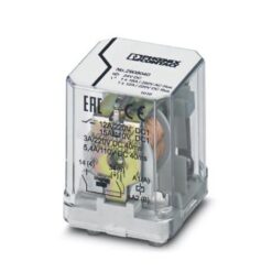
Industrial Relays
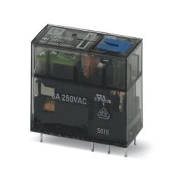
Industrial Relays
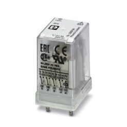
Industrial Relays
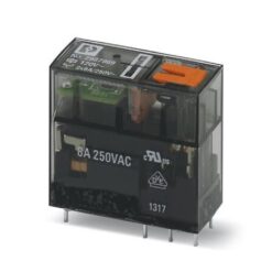
Industrial Relays
Industrial Relays

Industrial Relays
Industrial Relays
UMK-5REL/KSR-24/230/KRK5S/MSTB 2908666 PHOENIX CONTACT Relay Module