


PSR-MC38-2NO-1DO-24DC-PI 1009832 PHOENIX CONTACT Safety relay for emergency stop, safety doors and light gri..
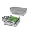
PSR-MC38-2NO-1DO-24DC-PI 1009832 PHOENIX CONTACT Safety relay for emergency stop, safety doors and light gri..
Safety relay for emergency stop, safety doors and light grids up to SILCL 3, Cat. 4, PL e, 1- or 2-channel operation, automatic or manual, monitored start, 2 enabling current paths, 1 signal output, TBUS interface, U
Liên hệ:
Key Commercial Data
| Orderkey | 1009832 |
|---|---|
| Packing unit | 1 pc |
| Catalog page | Page 223 (C-6-2019) |
| GTIN | 4055626482712 |
| Weight per Piece (excluding packing) | 180.000 g |
| Custom tariff number | 85371098 |
| Country of origin | DE (Germany) |

Note
| Utilization restriction | EMC: class A product, see manufacturer’s declaration in the download area |
|---|
Ambient conditions
| Ambient temperature (operation) | -20 °C … 55 °C (observe derating) |
|---|---|
| Ambient temperature (storage/transport) | -40 °C … 70 °C |
| Max. permissible relative humidity (operation) | 75 % (on average, 85% infrequently, non-condensing) |
| Max. permissible humidity (storage/transport) | 75 % (on average, 85% infrequently, non-condensing) |
| Maximum altitude | ≤ 2000 m (Above sea level) |
Power supply
| Designation | A1/A2 |
|---|---|
| Rated control circuit supply voltage US | 24 V DC -15 % / +10 % (provide external protection) |
| Rated control supply current IS | typ. 75 mA |
| Power consumption at US | typ. 1.8 W |
| Inrush current | < 4 A (Δt = 3 ms at Us) |
| Filter time | 20 ms (at A1 in the event of voltage dips at Us) |
| Protective circuit | Serial protection against polarity reversal Suppressor diode |
Digital inputs
| Input name | Sensor circuit |
|---|---|
| S10, S12, S13, S22 | |
| Description of the input | safety-related sensor inputs |
| NPN (S10, S12, S13), PNP (S22) | |
| Number of inputs | 4 |
| Input voltage range “1” signal | 20.4 V DC … 26.4 V DC |
| Inrush current | < 40 mA (typ. with USat S10) |
| < 300 mA (typ. with USat S12, Δt = 150 ms) | |
| < 3 mA (Typically with USat S13) | |
| > -300 mA (Typically with USat S22, Δt = 150 ms) | |
| Current consumption | 40 mA (typ. with USat S10) |
| 45 mA (Typically with USat S12) | |
| 3 mA (Typically with USat S13) | |
| -35 mA (Typically with USat S22, Δt = 150 ms) | |
| Filter time | 2 ms (At S10, S12, S13; test pulse width of low test pulses) |
| 1 ms (At S10, S12, S13; test pulse rate of low test pulses) | |
| No brightness test pulses / high test pulses permitted. | |
| Max. permissible overall conductor resistance | 50 Ω |
| Concurrence input 1/2 | ∞ |
| Protective circuit/component | Suppressor diode |
| Input name | Start circuit |
| Y1, S34, S35 | |
| Description of the input | non-safety-related |
| NPN | |
| Input voltage range “1” signal | 20.4 V DC … 26.4 V DC |
| Inrush current | < 60 mA (Typically with USat Y1, Δt = 150 ms) |
| < 270 mA (Typically with USat S34, Δt = 15 ms) | |
| < 80 mA (Typically with USat S35, Δt = 25 ms) | |
| Current consumption | typ. 10 mA (Typically with USat Y1) |
| typ. 34 µA (Typically with USat S35) | |
| Max. permissible overall conductor resistance | 50 Ω |
| Protective circuit/component | Suppressor diode |
Relay outputs: enabling current path
| Output name | Enabling current path |
|---|---|
| 13/14, 23/24 | |
| Output description | safety-related N/O contacts |
| 2 NO contacts each in series, without delay, floating | |
| Number of outputs | 2 (undelayed) |
| Contact type | 2 enabling current paths |
| Contact material | AgSnO2 |
| Switching voltage | min. 10 V AC/DC |
| max. 250 V AC/DC (Observe the load curve) | |
| Limiting continuous current | 6 A |
| Inrush current | min. 10 mA |
| max. 6 A | |
| Sq. Total current | 72 A2(observe derating) |
| Switching capacity | min. 100 mW |
| Switching frequency | max. 0.5 Hz |
| Mechanical service life | 10x 106cycles |
| Switching capacity according to IEC 60947-5-1 | 5 A (24 V (DC13)) |
| 5 A (250 V (AC15)) | |
| Output fuse | 10 A gL/gG |
| 4 A gL/gG (for low-demand applications) |
Alarm outputs
| Designation | Y30 |
|---|---|
| Output description | PNP |
| non-safety-related | |
| Number of outputs | 1 |
| Voltage | approx. 23.9 V DC (Us– 0.1 V) |
| Current | max. 100 mA |
| Maximum inrush current | 500 mA (Δt = 1 ms at Us) |
| Protective circuit/component | Suppressor diode |
Times
| Typical pickup time at US | 200 ms (when controlled via A1) |
|---|---|
| Typical response time at US | 200 ms (automatic start) |
| 30 ms (manual, monitored start) | |
| Typical release time at US | 25 ms (when actuation is via the sensor circuit) |
| 60 ms (when controlled via A1) | |
| Restart time | < 1 s (Boot time) |
| Recovery time | < 500 ms |
General
| Relay type | Electromechanical relay with forcibly guided contacts in accordance with EN 50205 |
|---|---|
| Nominal operating mode | 100% operating factor |
| Net weight | 169.38 g |
| Mounting position | vertical or horizontal |
| Mounting type | DIN rail mounting |
| Assembly instructions | See derating curve |
| Degree of protection | IP20 |
| Min. degree of protection of inst. location | IP54 |
| Housing material | PBT |
| Housing color | yellow |
| Operating voltage display | 1 x green LED |
| Status display | 4 x green LEDs |
Connection data
| Connection method | Push-in connection |
|---|---|
| pluggable | no |
| Conductor cross section solid min. | 0.2 mm² |
| Conductor cross section solid max. | 2.5 mm² |
| Conductor cross section flexible min. | 0.2 mm² |
| Conductor cross section flexible max. | 2.5 mm² |
| Conductor cross section AWG min. | 24 |
| Conductor cross section AWG max. | 14 |
| Stripping length | 10 mm |
Safety-related characteristic data
| Stop category | 0 |
|---|---|
| Designation | IEC 61508 – High demand |
| Safety Integrity Level (SIL) | 3 |
| Designation | IEC 61508 – Low demand |
| Safety Integrity Level (SIL) | 3 |
| Designation | EN ISO 13849 |
| Performance level (PL) | e |
| Category | 4 (5 A DC13; 5 A AC15; 8760 switching cycles/year) |
| Designation | EN 62061 |
| Safety Integrity Level Claim Limit (SIL CL) | 3 |
Standards and Regulations
| Designation | Air clearances and creepage distances between the power circuits |
|---|---|
| Standards/regulations | DIN EN 50178 |
| Rated insulation voltage | 250 V |
| 250 V | |
| Degree of pollution | 2 |
| Overvoltage category | III |
| Shock | 15g |
| Vibration (operation) | 10 Hz … 150 Hz, 2g |
| Conformance | CE-compliant |
Classifications
Sản phẩm tương tự
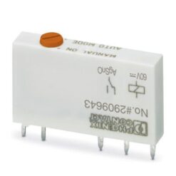
Industrial Relays
Industrial Relays
Industrial Relays
REL-MR-110DC/21-21AU/MS 1013727 PHOENIX CONTACT Single relay
Industrial Relays
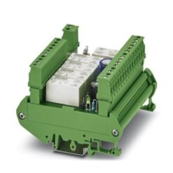
Industrial Relays
UMK-5REL/KSR-24/230/KRK5S/MSTB 2908666 PHOENIX CONTACT Relay Module
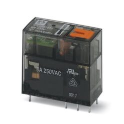
Industrial Relays
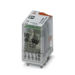
Industrial Relays